
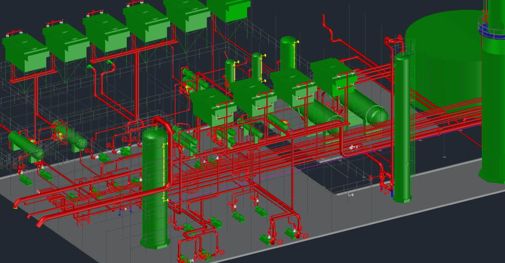

🔧 The Difference Between AutoCAD 2D and AutoCAD P3D
A Journey into the World of Industrial Diagrams and Systems
🟢 The importance of industrial diagrams lies in defining the start and end of the process / mechanical equipment and other fittings connected to the line / the data for each element, flow directions, temperatures, and pressures. This helps everyone involved in the project — regardless of their rank — understand the required data and knowledge for the industrial line.
🎨 P&ID Symbology — Industrial Symbols
🟢 The elements we add to the project follow a global standard implemented in AutoCAD Plant 3D, through which elements are designed and programmed in a way that distinguishes them from other standards. Therefore, from the very beginning of work on the project, the used standard must be determined first — from it, we can access all elements designed according to it.
PIP (Process Industry Practices)
ISO (International Organization for Standardization)
ISA (Instrument Society of America)
DIN (Deutsches Institut Fur Normung e. V.)
JIS-ISO (Japanese Industrial Standards)
⚙️ Add Equipment
🟢 We can control the visibility level of the toolbar color through the Options window, which we can access by calling the command:
Options — OP
🟢 By typing OP on the keyboard and pressing Enter, then from the Display tab in the dropdown menu next to the color map, we choose the level we want.
🔩 Adding Valves
🟢 To start adding valves to our project (P&ID), we first make sure the standard is selected and then display its tools, from the Valves tab (Valves).
🟢 AutoCAD Plant 3D provides us with multiple types of valves according to the selected standard. We select the valve and click on it to activate the tool, then go to the drawing area and place it on the line (Schematic Line) at the appropriate place.
🟢 You will notice that after placing the valve, its size and code (Code) appear automatically. We can change the valve’s code as we wish and also number it using the well-known method.
🎛️ Control Valve
🟢 The control valve is used to control the flow. It is divided into two parts (the body and the actuator), and both have different types. Before starting to install the control valve using Plant 3D, an electrical signal line is added first. It can be accessed from the toolbar, then choosing the appropriate tab for industrial lines as follows:
TOOL PALETTES → P&ID PIP \ Lines \ Instrument Lines \ Electric Signal
🟢 Then it is added to the tank in the design. You will notice that the line carries different properties from other lines, as every line drawn in the industrial diagram has its own thickness, color, and name depending on its type. Note that these properties can be changed as we wish.
🎓 Enroll in the Course
💰 Only $10


Pingback: Spec Editor – easy2learn
Pingback: Schematic Line Edit in AutoCAD Plant 3D – easy2learn
Pingback: Publishing in AutoCAD Plant 3D 2017 – easy2learn
Pingback: Isometric Views in AutoCAD Plant 3D – easy2learn
Pingback: Orthographic Views in AutoCAD Plant 3D – easy2learn
Pingback: Data Manager in AutoCAD Plant 3D – easy2learn
Pingback: AutoCAD Plant3D User Interface – easy2learn
Pingback: Introduction of AutoCAD Plant 3D – easy2learn
Pingback: Projects in AutoCAD Plant3D – easy2learn
Pingback: Process and Instrumentation Diagrams (P&ID) – easy2learn
Pingback: 3D Model in AutoCAD Plant3D – easy2learn
Pingback: AutoCAD Plant3D| Report Creator – easy2learn
Pingback: Thanks for Joining to easy2learn school – easy2learn